Making a Compass That Points to the Nearest Taco Restaurant

The taco compass
Continuing my trend of making useless inventions, I decided that I needed help finding places to eat one of my favorite foods, tacos.
Planning
The first decision to make was the high-level architecture of the project, so I had a few questions to answer:
- Would it be standalone, or would it require a phone?
- Would it run on a micro-controller, or a single board computer like a Pi? A mix?
- What sensors do I need to accomplish an absolutely positioned arrow?
- How does the arrow work?
- What parts are easy/cheap to source?
I wanted the device to be standalone, so I could hand it off to someone and have them use it, without needing an internet connection. I first searched for the components I thought would cost the most, to constrain my budget. I found that all-in-one GPS modules were fairly expensive, but there were cheap USB options on Amazon. This motivated my decision to limit myself to a single Raspberry Pi Zero due to the relatively low speed requirements, however running this without an RTOS is not necessarily optimal if I wanted to run high-frequency real-time motion fusion algorithms for an IMU.
Prototyping the Arrow Movement

Compass held over a 3d printed bar with embedded magnets
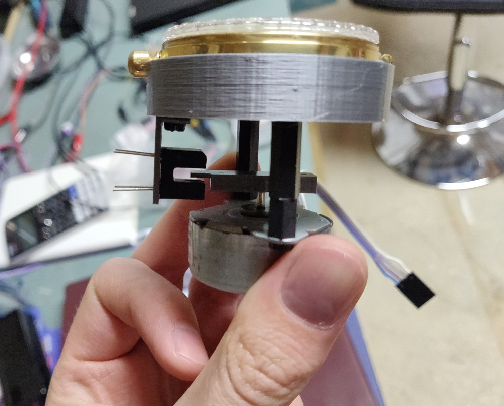
I wanted the arrow to be able to spin around continuously, but servos are typically constrained to an angle range, and have gearing which I would not need. I decided a stepper motor with a way to absolutely calibrate it with a beam-break sensor would be optimal.
Originally, I had though it would be really interesting to have a compass that instead of pointing north, it pointed to tacos. I whipped up a quick model in OpenSCAD to prototype this with the stepper motor and beam-break sensor.
Then I hooked it up to an Arduino to quickly test it.
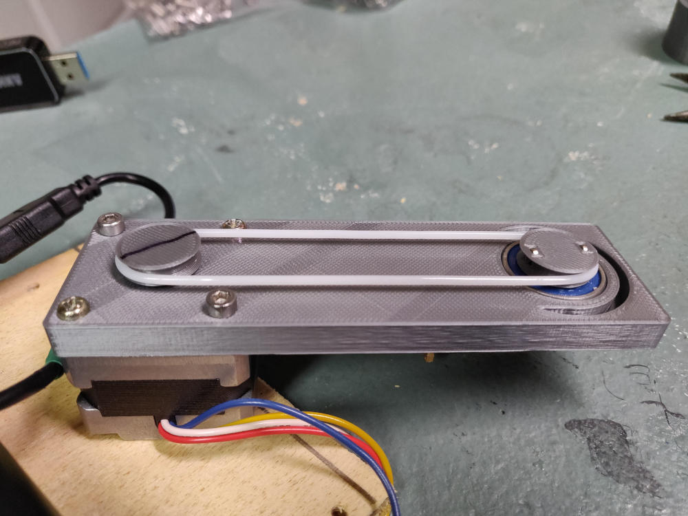
I quickly realized that the motor’s magnetic field would impact the digital compass in the IMU, so I created another design that placed the motor as far as it could be from the IMU’s planned location.

Belt design to distance the motor
(side note, TPU makes a pretty decent belt for a quick hack for low-load)
It turned out that the major issue was not the motor (even though it produced a significant field), because it was relatively consistent. It was the dynamically moving field of the moving magnets. I settled for directly attaching a plastic arrow to the stepper motor shaft.
Electronics
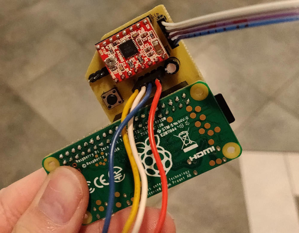
With the overall design in mind, I decided to start work on the electronics. I chose a USB GPS and a MPU-9250 9 axis IMU sensor (accessible over I2C and SPI), a standard stepper motor driver board that supports low supply voltages (5v from USB), and a beam-break sensor. The PCB just needed to connect everything together, and I used 0.1” headers for all the wiring.
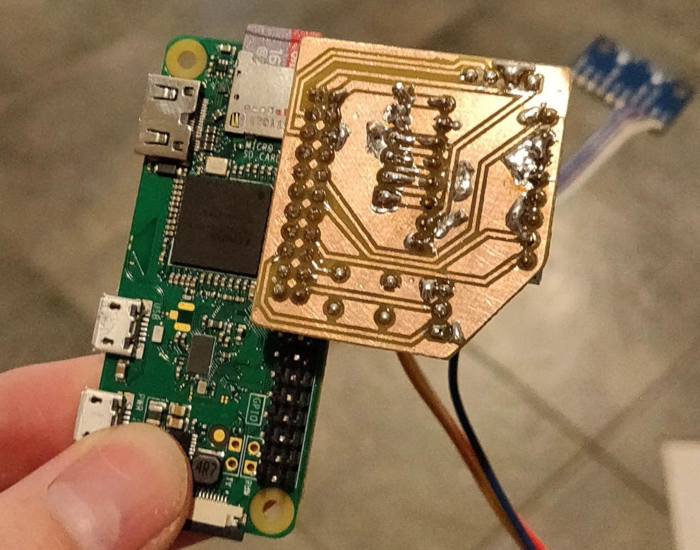
I used KiCad again to produce the simple schematic and quickly settled on a form-factor. Since I can only reasonably etch single-side boards in my workshop, and it would save space, I decided to have the board hang off the edge of the PI, all the components on one side.
Software
I used the Google Places API to scrape JSON of taco places around my area, writing shell scripts to query for the tag “taco”.
I decided to prototype the software in Python, knowing that it was likely a better idea to write the final code in C, considering the fact that my processor was literally encased in insulation. I used a 9-dof motion fusion library that I found on GitHub. My software creates a process (to avoid Python’s interpreter lock) for the stepper motor, the GPS, the IMU unit, and the main targeting logic. These communicate through shared memory, where the sensor threads update their yaw / location values, the main process sets the target angle, and the stepper process constantly attempts to move to the target angle.
I then created a test taco restaurant in the center of a pond nearby and had a walk around it:
Frame and Assembly
I went about designing the frame by revisiting FreeCad, since it was a relatively simple model. After measuring twice, test fits, and failed 3d prints, It all fit.
Final Thoughts
During prototyping the software in Python it quickly became apparent that an RTOS, or at least a dedicated motion processor would be useful. There is lots of overhead in polling the sensor over i2c for updates, filling FIFOs in the C++ motion fusion library, and calling the bindings from Python. There was also was a lack of deterministic scheduling behavior which may be useful for robustness.
Also, due to the lower polling frequency and basic motion fusion algorithm, the sensor tended to drift, and drastically went out of calibration in new environments, however the behavior was similar to the accuracy of my phone’s compass without re-calibration. It’s clear a continuously calibrating motion fusion algorithm was necessary (does waving your phone in a goofy figure 8 ring a bell?).
Altogether, I’m happy with the results, it may be worth looking into something like the Ultimate Sensor Fusion Solution to drastically increase the heading accuracy with a dedicated motion fusion processor, or try to write my own live-calibration routines and heading estimation. For example: if you assume the person is pointing the compass in a particular direction, the GPS location history could be used as a heading estimator.


