1 / 16
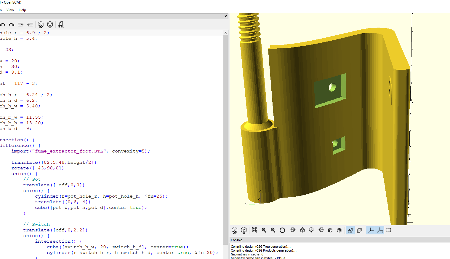
First I found a model for a fume extractor, and modified the base to accept a switch and potentiometer using OpenSCAD (Model from) https://www.thingiverse.com/thing:1436781
2 / 16
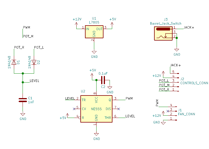
Decided to pick up KiCAD for this project. Using PWM 555 timer circuits I found online, and some capacitor and diode calculations, I figured out what values would get me in the ballpark of 25Khz which is the PWM frequency for 4 pin PC fans.
3 / 16
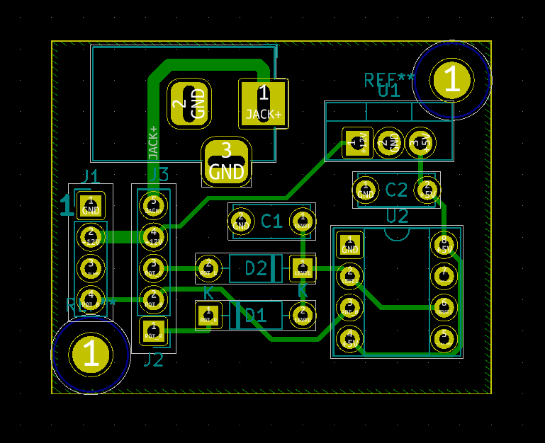
I then laid out the board. KiCAD is growing on me, I really like it now!
4 / 16
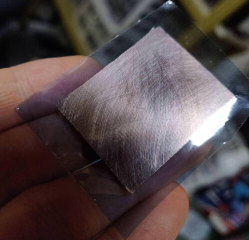
I'm going to use a UV sensitive film lamination process to save money. After frustratingly picking at the edges and a satisfying peel, you laminate this film on to the bare copper board. I put a piece of paper in between the board and the laminator, to protect the plastic.
5 / 16
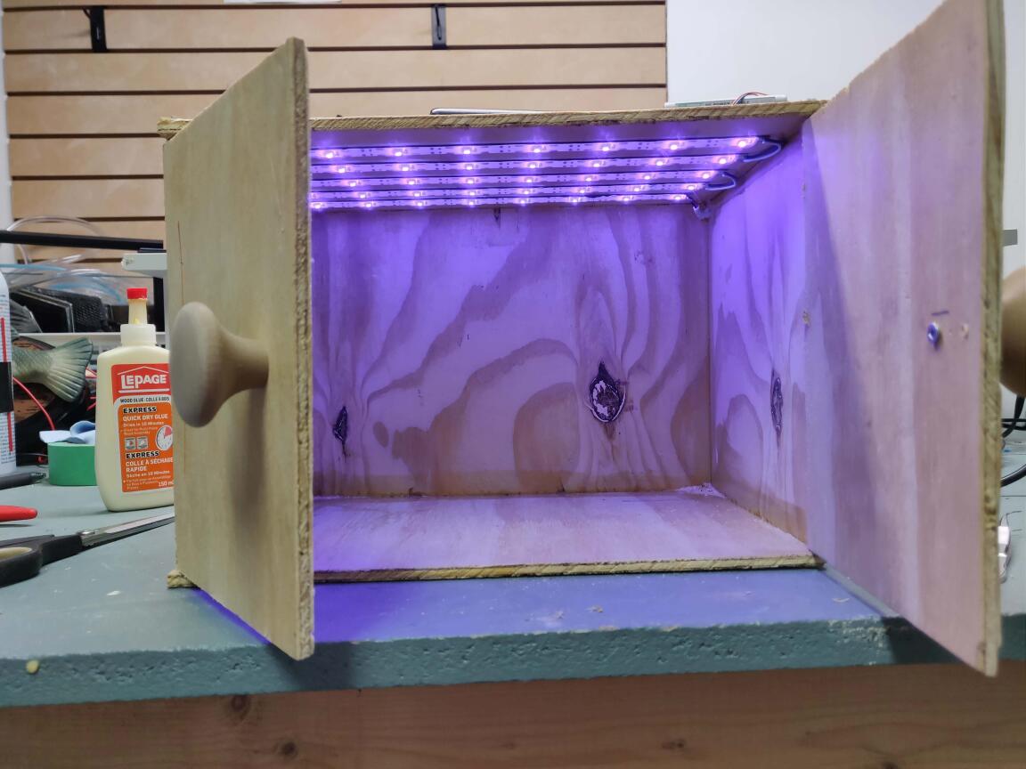
I built this UV curing box using a UV led strip from amazon and some wood PLA 3d printed knobs. It's pure garbage construction, but does the job. Just plugs in to a USB power bank with a cord on the top.
6 / 16
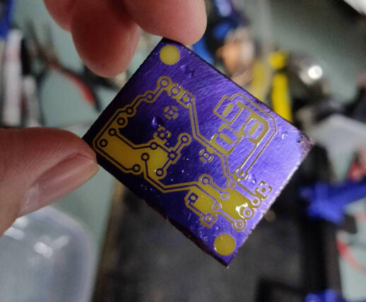
Exposing the board with some mineral oil between a laser printed transparency sheet (1 layer) to help it stay put but not stick. UV LEDs take about 15 minutes to get a good exposure.
7 / 16
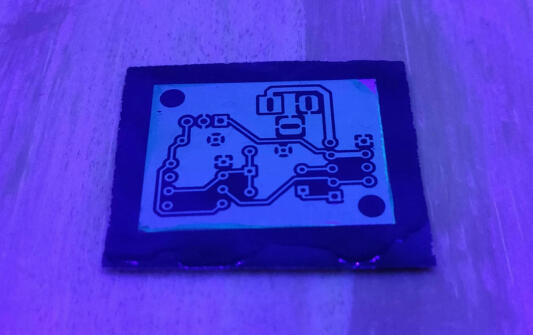
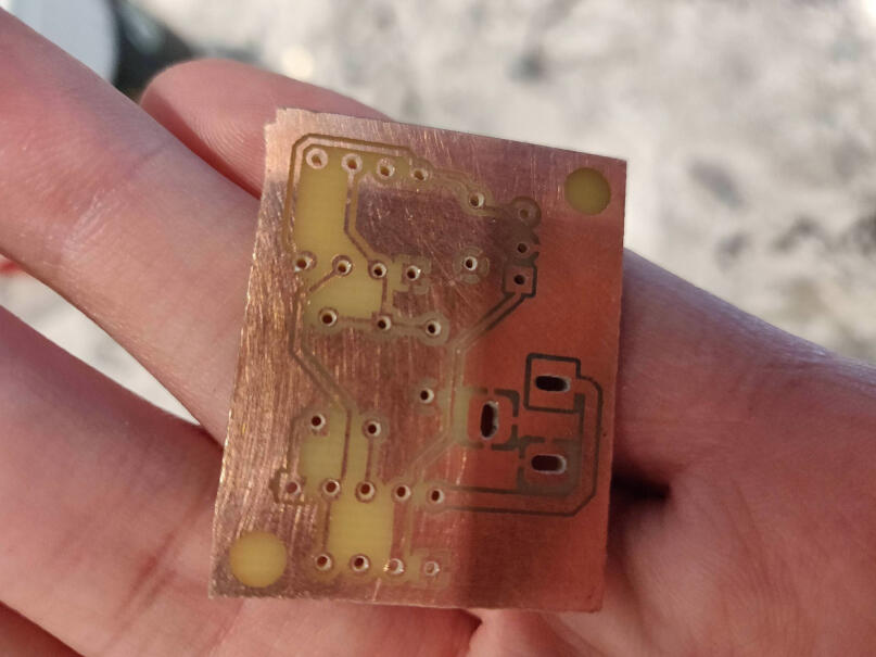
Here's it after developing in some sodium carbonate. Don't waste your money buying that stuff, just heat up baking soda and it converts. The edges had peeled because of a couple blunders on my end, so I filled them in with sharpie.
8 / 16
At the bottom corner here, one of the square pads gets fairly close to the ground plane due to an artifact in exposing.
9 / 16
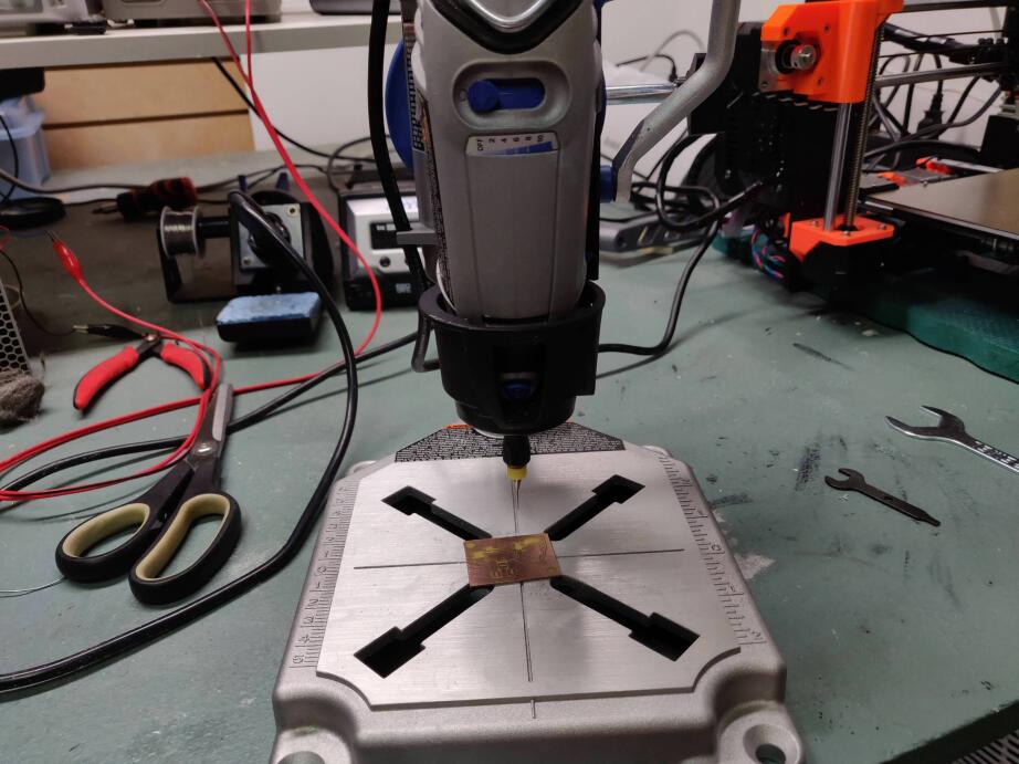
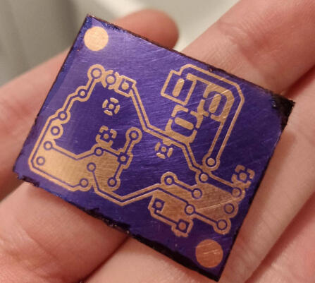
After removing the cured film with acetone, it was time to drill. It's not the best setup, but it works, and it only has destroyed my smallest bits so far after around 80 holes drilled. Ordering a Chinese drill motor with supposedly better bearings to rig up to the press for better run-out.
10 / 16
After a bit of practice I'm okay drilling this without making mistakes.
11 / 16
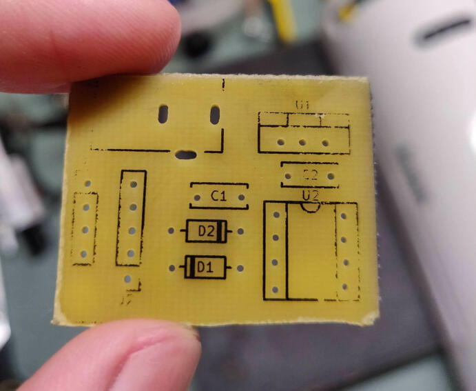
I tried 'silkscreening' by exporting the silkscreen layer, increasing all the line widths, laser printing onto shiny magazine paper, and then running it through a laminator with the board many times. It seems to work very well. Ignore everything except the center, since I accidentally ripped the edges off halfway through.
12 / 16
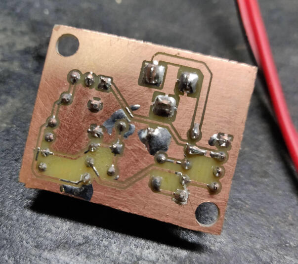
Soldered and fixed short on bottom right with a box cutter. May experiment with UV curing mask, but it seems not worth the effort.
13 / 16
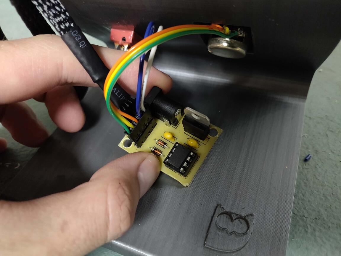
Test fit and operation, works perfectly
14 / 16
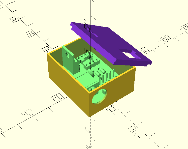
Exported 3d board model using StepUp freecad addon, designed a case in OpenSCAD to fit the board
15 / 16
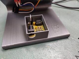
Two mounting points on the diagonals screw into brass inserts below the case, pushed in to the base using a soldering iron. I didn't have the foresight to design this into the base before.
16 / 16
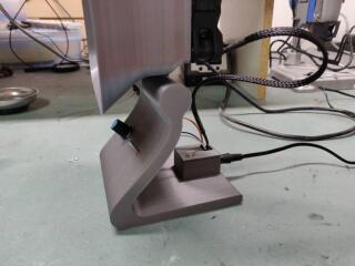
Everything fit and plugged in.
❮
❯